Have you ever come across a fitting like one of these on a set of plans and
wondered what the designer was smoking when he drew that? Is it possible to
make something like this in my home shop? I have personally read a lot of books
and magazine articles on homebuilt aircraft construction and have never come
across anything for making these. I have four similar to these to make for my
N3 Pup and until recently I didn't have any ideas how to do it. Then it
happened. I went and bid a job that needed them and I won the job. Time to come
up with something fast. I called Stan Blankenship on the phone for advice. Stan
has been involved in the aircraft industry longer than I have been alive and
has more knowledge about making aircraft parts than anyone I know. He tells me
"Get a pin the right size and just wrap it around". Thanks Stan. I
could have thought of that myself. Then I remembered a tool I purchased for
bending music wire for a landing gear on a radio control airplane. It was just
a small plate with 2 pins pressed in. It had a round handle with a hole to
pivot on one of the pins in the plate and a pin pressed through the handle.
Thread the wire through the pins, crank the handle around and you can make
pretty little bends all day long. Thanks again Stan, really!
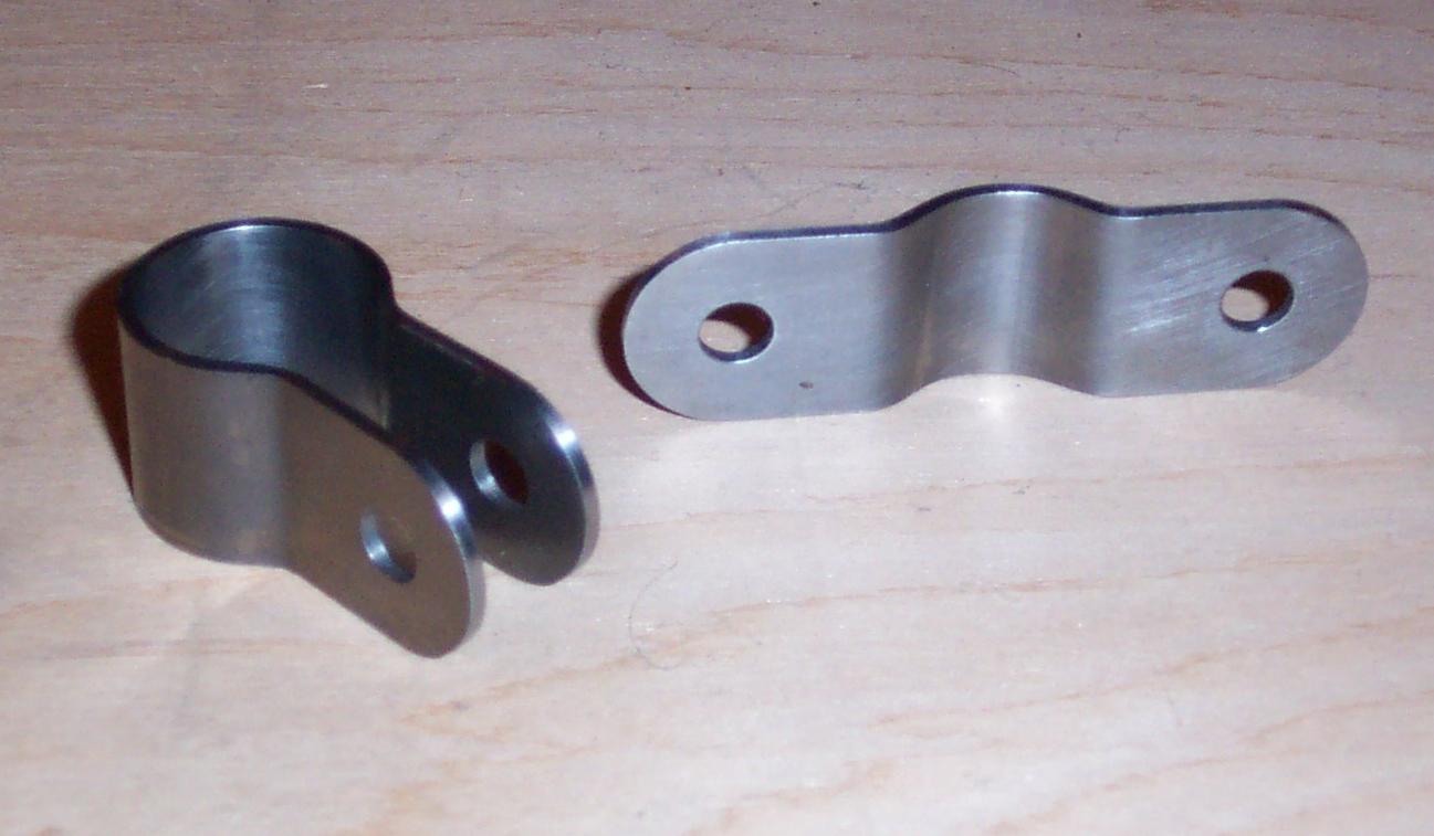
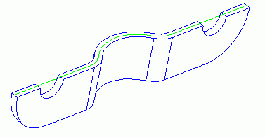
Ok, we have a direction to go but how do we implement it? The two fittings
pictured above are very similar. The parts are made of .063" 4130-N. They
both get welded to ¾" tubing. One is wrapped all the way around with
two flanges .375" apart. The other is only wrapped half way with two parts
welded to the ¾" tube opposite each other to form two .375"
gaps. The distance from the center line of the .250" hole in the strap to
the center line of the ¾" tube is the same for both parts. I also had
a close tolerance for the .375" gap because a spherical rod end gets
bolted between the flanges and after welding, the flanges are not going to flex
much. We need an accurate flat pattern and precision forming to make a quality
part.
The techniques I am going to describe can be easily adapted for the home shop.
It is very helpful to have a CAD system of some sort for the flat pattern
calculations and to plot a full-scale outline of the profile. If you have the
math background the calculations can be performed with a scientific calculator.
You could also manually lay the profile out full size and through a process of
trial and error, come up with a flat pattern by measuring and guessing. Making
scrap is very expensive for me, so I prefer to invest the time up front to make
accurate parts.
Bend allowance tables don't work well for these parts because there is a
.375" radius for the large bend around the ¾" tube going
directly into a .125" radius bend for the flange. You have to know the
number of degrees the bend is going through to use the bend allowance tables.
If you are willing to wade through the math necessary to figure the angle of
the arcs, go for it. I prefer to use a CAD system. It's just like a large
pocket calculator that does most of the work for you. |
 |
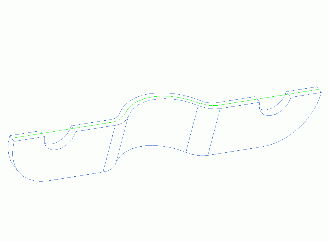
| The first thing we need to draw is the profile of the part. I usually start
with a full 3-D solid model of the part I am going to make. The picture above
is a screen shot of the solid model I had on my computer. On my screen the
background is normally black and the part image is much higher quality, but I
wanted them to print without using all your toner or take 3 days to download.
|
 |
| The next thing required for this part is to split the solid in half as
shown above. This is a very easy thing to do in a solid modeler but if you are
doing a 2-D wire frame drawing, just draw the profile of the part through the
center to start with. Now for the beauty part of your CAD system. Offset the
profile .4466 * T (material thickness) from the inside of each bend. This is a
close approximation of the neutral axis of the bend and is represented by the
green line above. You can't really see it well in the image above but the ends
of the green arcs do not line up (click the image for a larger version). This
doesn't matter though because all we need to know is the length of the green
entities to find the overall length of our flat pattern. Most CAD systems have
a function to analyze the length of any entity. Use it for each one and add
them all together. You now have the overall length of your flat pattern. |
 |
| The next step is to lay out the flat pattern. If you are only making one
part, you can lay it out directly on your material. I do it in my CAD system
again because I cut the flat pattern on a CNC mill and I need a model for
programming. Cut out your parts to get ready for forming. You can cut the
radius on the end and drill the two holes after forming if you want. If you can
cut the flat pattern accurately and bend the two .125" bends accurately,
it is easier to drill and cut the radius first. |
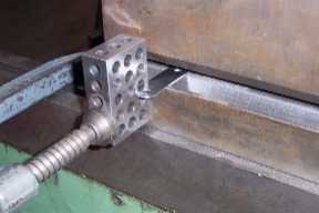 |
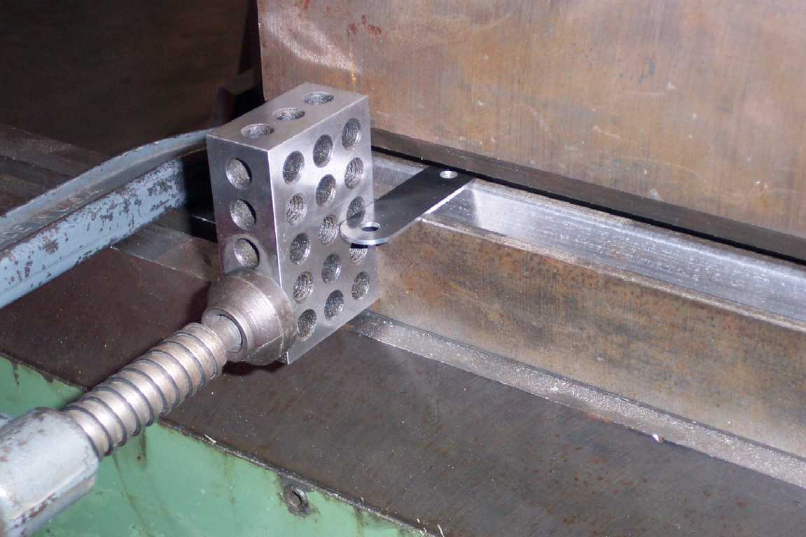
| Time to form the part. The two .125" bends need to be located very
accurately on the flat pattern in order for the .375" gap to come out
right. If you can imagine, miss-locating the bends by a small amount will make
a large change in the gap. You should also concentrate on making both bends the
same. I prefer braking parts on a press brake. Parts tend to slip in a leaf
brake and the bends will be miss-located. You could also form the part in a
vise but it is very hard to locate the bend correctly. In a press brake there
is a backstop to locate the bend accurately and consistently. Because the part
has a radius on the end, I clamped a 1-2-3 block to the female die to square
the part to as you can see above. |
 |
| I plotted out the profile full scale to check my parts against. Use some
scrap material to check your setup before forming your good parts. If the scrap
has square corners, it is very easy to check against the plotted profile
because the square corner will be down against the plot. You don't have to
eyeball straight down and guess at the length of the flange if the corners are
square. |
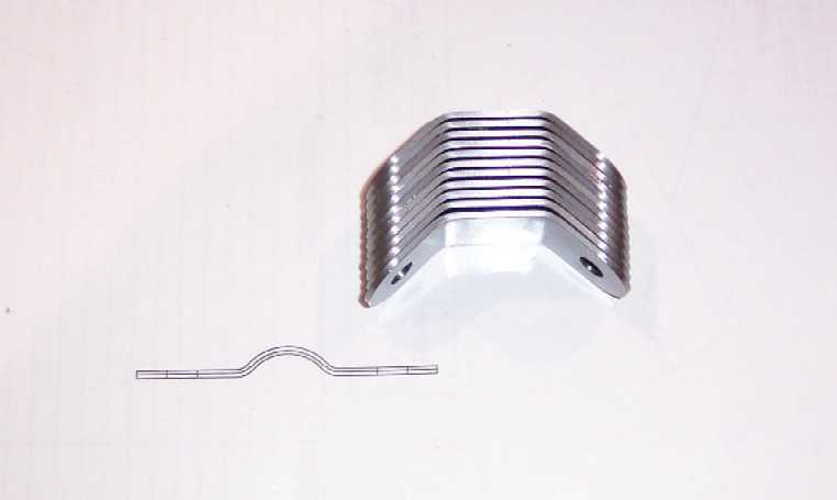 |
| Here are eleven parts ready for final forming. See how consistently the
press brake forms the parts. |
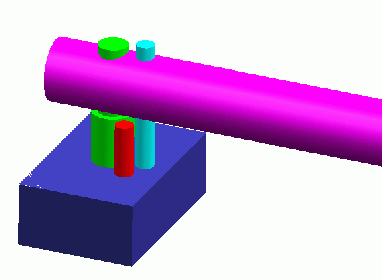 |
| This is a model of the form tool for forming the .375" radius. The
green pin is what determines the size of the radius. If you have ever formed
any sheet metal you know that you have to over-form the material because it
springs back. The radius of the bend springs back as well as the angle of the
bend. The larger the bend radius, the more the bend radius springback becomes a
factor for making accurate parts. I have springback information in my
Fabricating Precision Sheet Metal Aircraft Parts article. For this .375"
radius I made the forming pin .700" diameter. The red pin is pressed into
the blue block. It holds the material in place for forming. The cyan pin is
pressed in the handle and does the forming when you rotate the handle. |
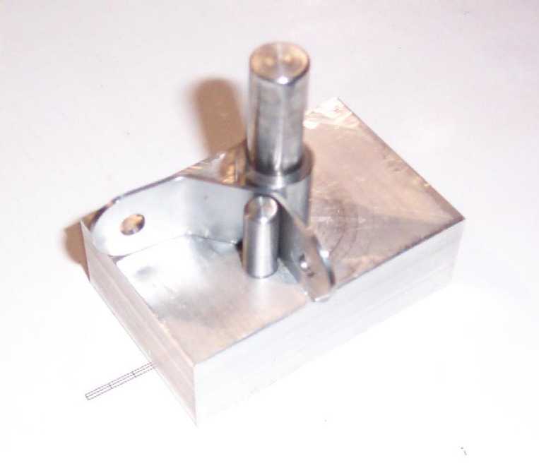 |
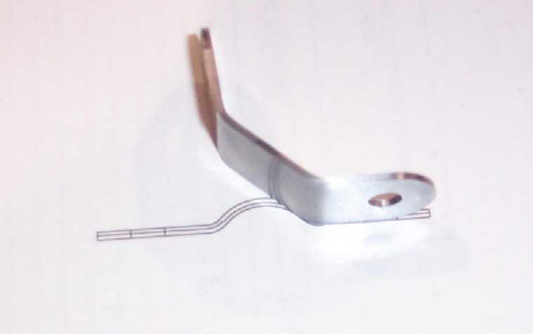
| Here is one of the parts on the tool. The distance between the .700"
pin and the .250" pin is .063", the material thickness. The farther
the small pin is from the large pin, the farther the .375" formed radius
will start from the .125" bend. When forming the part, do not wrap the
part completely from the first side. It will not form the part completely to
the second .125" bend if you do. Start the .375" form on the first
side, and then flip the part to finish the form from the second side. |
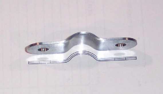 |
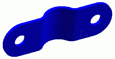
| This is the finished product setting above the full sized plot. The other
strap was formed with the same setup, it was just formed farther around. This
technique can be adapted to other parts as well. I hope you find it useful.
|
 Strap Fitting