|
 |
| Fabricating Precision Sheet Metal Aircraft Parts
|
This is a specialty of mine so this section will be fairly extensive. You
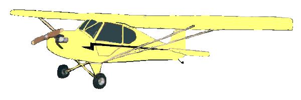
may be thinking that a Preceptor Pup is a rag and tube airplane and the sheet
metal work makes up a very small portion of the airplane but when you take that
innocent piece of sheet metal and try to put a bend in it, things can get
complicated in a hurry. I will try to keep my explanations as simple as I can
but because the process can be complicated this will take some effort for me to
explain completely and for you to follow along if you have limited experience
with sheet metal. Don't be to discouraged though, you can do anything you put
your mind to and this isn't brain surgery.
We should start our discussion by taking a look at the state of the art in
aircraft sheet metal manufacturing and work our way toward the information and
techniques you can use in your home shop. I will supply the math you need and I
also have an Excel spreadsheet available so your computer can do some of the
hard stuff.
So what is the ultimate process available for the design and manufacturing of
your dream plane? Lets start with an unlimited budget. Throw in a large team of
experienced aerospace engineers, the latest greatest CAD/CAM/CAE software,
every piece of manufacturing equipment you can imagine, shake it all up and
what do you get? Well it probably won't be state of the art. My experience with
the local aircraft manufacturers suggests that they're still making sheet metal
airplanes the same way they did in the forties for the most part. The
technological advances in computers and manufacturing equipment have definitely
been put to good use, but you will have to look somewhere else for the leading
edge.
So what does it take? Lets start by creating a complete, accurate 3D solid
model of the entire airplane with the best software you can find. Lets make
sure to model every rivet location, every wire, hose and radio. Make sure to
finish the computer model before you start making parts because if you don't
you will make a lot of them again. I know you're anxious to get some parts in
your hands but it will go faster in the end if you finish the details on your
model first.
Ok, you have a model, it has been approved by everyone important, now what? For
the sheet metal parts, we are going to need to determine the manufacturing
processes necessary to fabricate them. The majority of the parts can probably
be brake formed, roll formed or hydro formed and these are the processes I will
concentrate on. Parts that get draw formed, stretched or formed with a drop
hammer are beyond the scope of what you would normally find on most homebuilt
aircraft so they won't be dealt with here.
Sheet metal normally comes in flat sheets, so we need flat patterns of all the
parts to cut out of those sheets. We will be discussing how to develop accurate
flat patterns. After the flat patterns are made, we'll need some tooling to
form the parts. We will create 3D computer models of our form blocks directly
off the models of the parts for complete accuracy. Be sure to allow the proper
spring back for the condition the material is in at the time of forming. Next
we'll cut the form blocks on our CNC mill and cut our flat patterns on our CNC
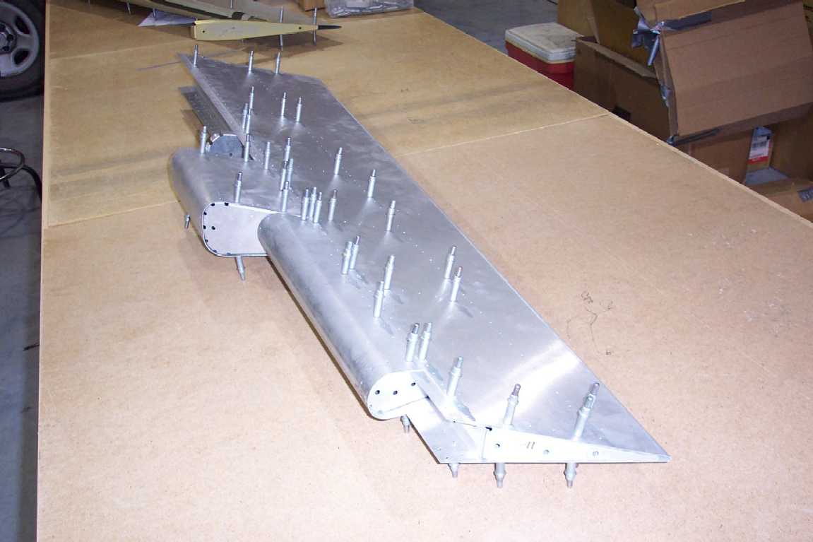
router, then form the parts. Parts fabricated this way can be held consistently
to tolerances plus or minus .005" on the webs and flanges. You didn't
forget to pre-drill for all your fastener locations did you? OOPS! This
is where the major aircraft manufacturers drop the ball. With the accuracy of
the manufacturing equipment available today and the power available in the
computer on your desk, there shouldn't be any excuse for being unable to
pre-drill all the holes should there? It sure would be nice to be able to
gather all your parts, cleco everything together and start riveting without
having to rely on some massive assembly fixture to locate all your parts,
wouldn't it?
Wait a minute. Doesn't Van's Aircraft supply most of their parts for the RV-7,
RV-8 and RV-9 pre-drilled just as we have been talking about? I'm sure there
are others doing the same thing. What's wrong with everyone else? We'll try to
determine that later but for now we will get into the nuts and bolts of
developing flat patterns.
Lets start with some definitions. |
 |
FLAT PATTERN - The outline definition of the part in it's flat state before
forming. This can be a physical drawing or template or a computer model. Lets
go ahead and include all the fastener locations.
OUTSIDE MOLD LINE or OML - The intersection of two outside surfaces of a part
extended past the bend radius. This intersection is not actually something that
can be measured on a part directly unless the bend angle is 90 degrees. Most
drawing dimensions for formed sheet parts are to the outside mold line.
INSIDE MOLD LINE or IML - This is the same as the OML except using 2 inside
surfaces instead. This is also the form block line.
BEND TANGENT LINE - The line created where the radius of the bend meets (is
tangent to) either flange. There are 2 bend tangent lines for each bend.
CENTERLINE OF BEND - The line midway between the two bend tangent lines. This
is useful for brake forming bends on a press brake.
FLANGE LENGTH - The distance measured from the edge of the flange to the
outside mold line.
NEUTRAL AXIS - The arc through the bend between the bend tangent lines where
the metal neither stretches nor compresses.
T - The sheet metal thickness.
R - The bend radius. This is always the inside radius, not the outside.
a - The angle of the bend in degrees.
K=tan(a/2)
KT - The distance between the OML to the IML projected to the plane of one of
the surfaces. KT=[tan(a/2)]T or KT=K*T
BA - Bend allowance or the length of the neutral axis. BA=a(.01743R +
.0078T)
BT - The distance from the OML to the bend tangent line. BT=K(T + R)
D - Setback. The amount of material saved by going through a radius instead of
a square corner on a bend. D=2BT - BA.
Lets go through the math for a simple bend. Say we need a part with a 90 degree
bend with two 1" leg lengths. We will be using .032 material with a .125
bend radius. The part needs to be 4" long. Lets start by listing what we
know.
T=.032
R=.125
a=90
Now we'll plug the numbers in our formulas.
K=tan(a/2)
K=tan(90/2)
K=tan(45)
K=1
BA=a(.01743R + .0078T)
BA=90*(.01743 * .125 + .0078 * .032)
BA=90*(0.00217875 + 0.0002496)
BA=90 * 0.00242835
BA=0.2185515
BT=K(T + R)
BT=1 * (.032 + .125)
BT=1 * .157
BT=.157
D=2KT - BA
D=2 * .157 - .2185515
D=.314 - .2185515
D=0.0954485
Not too difficult is it? It's just a little tedious. There are sheet metal
books available that have charts made up with the numbers calculated for each
of the common material thickness and bend radius combinations. The charts are
calculated for every 2 degrees of bend or so. I have created an Excel
spreadsheet that calculates this for you so you don't have to worry about
misplacing a little book. It is better than a book because you can plug in the
exact angle you are bending. If you want you can make up your own book by
printing this spreadsheet for each angle you need to bend. You can download it
here. Sheet Metal
Forming Table |
 |
All right, now we can layout our flat pattern. First draw a line 4 inches
long to represent one edge of our part (#1). Now draw another 4-inch long line
parallel to the first 1 inch away to represent the outside mold line (#2). From
there we draw another line that is offset our D distance of 0.0954485"
towards the first line from the second (#3). D is the amount of material
"saved" by going through a radius. From this line measure over
1" to the second edge (#4). What is represented by the four lines we have
drawn is the two edges on the outside and two outside mold lines separated by
the distance D. If there was no bend radius and you could bend a perfectly
square corner, the flat pattern layout would measure 2 inches wide for the two
1" legs by 4 inches long. Because you can't bend a square corner and our
bend radius is .125", our flat pattern should measure 1.9045515" x
4". Normally 3 decimal places is more than accurate enough for our
purposes so our flat pattern would measure 1.905" x 4.000".
MORE TO COME |
| |
| |
| |
|
 Sheet Metal